
Construction Schedule Excel Template: Master Schedule, CPM Logic and Fast-Track Bottlenecks
Build a master construction schedule in Excel that tracks CPM logic, total float, IBC 107.3.3 phased permits, utility transformer lead times, and TCO gates.
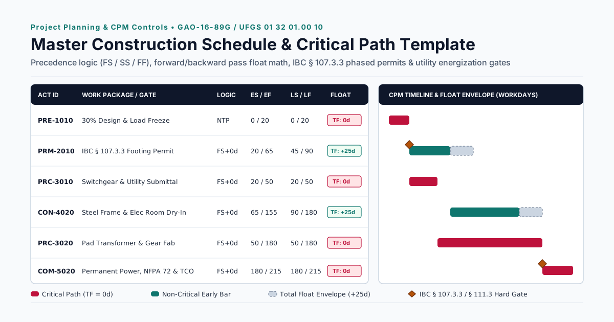
A static spreadsheet that colors calendar bars from hand-typed dates fails the moment a foundation permit review slips or a switchgear submittal requires rework. Without linked predecessor formulas and total float calculations, an unlinked construction schedule Excel template hides downstream delays until field crews stand idle and acceleration costs mount.
A functional master construction schedule must link every scope package—design milestones, municipal plan review, long-lead equipment fabrication, utility energization, field installation, and life-safety commissioning—into a continuous Critical Path Method (CPM) network. While design-build schedule compression overlaps early site and foundation work at 30% to 60% design under International Building Code (IBC) Section 107.3.3, fast-tracking shifts the controlling critical path away from structural framing and onto municipal permit gates, utility transformer delivery, and NFPA 72 acceptance testing. This guide provides the 14-column Excel CPM architecture, forward and backward pass formulas, a 20-row fast-track master schedule template, and the gate controls required across the project planning collection. Use it alongside what the preconstruction phase covers and the preconstruction risk checklist to lock interface dates before authorizing field work.
- 100% WBS Scope Coverage: Per the GAO Schedule Assessment Guide (GAO-16-89G), a baseline schedule must capture owner review windows, authority having jurisdiction (AHJ) plan checks, long-lead submittals, utility company work, and commissioning—not just on-site trade bars.
- Calculated Predecessor Logic Over Hard Dates: Every non-milestone row requires an explicit Precedence Diagram Method (PDM) relationship (
FS,SS, orFF), calculated Early Start (ES), Early Finish (EF), Late Start (LS), Late Finish (LF), and Total Float (TF = LS - ES). - Phased Release Boundaries: Fast-track delivery relies on 2024 International Building Code (IBC) Section 107.3.3 to release foundations before full construction documents are approved, placing code-compliance risk on the permit holder if structural grids or underground inverts shift.
- Non-Structural Critical Paths: Extended procurement windows documented by the U.S. Department of Energy Distribution Transformers Supply Chain Analysis and mandatory NFPA 72 National Fire Alarm and Signaling Code witness testing before Temporary Certificate of Occupancy (
IBC Section 111.3) routinely control final handover.
Why Static Excel Gantt Charts Fail as a Master Construction Schedule (and How to Structure a Logic-Driven Template)
Most downloadable spreadsheets marketed as a construction schedule Excel template are visual conditional-formatting calendars. An estimator or project manager types a start date into Column C, types a duration into Column D, and a grid of cells turns blue across the right side of the sheet. When the civil permit review takes 20 working days longer than planned, or a 480V main switchboard submittal is returned for revision, none of the downstream bars move automatically.
A true master construction schedule is a dynamic mathematical network, not a static drawing. Under the federal scheduling standards established in the GAO Schedule Assessment Guide (GAO-16-89G) and the USACE / NAVFAC UFGS 01 32 01.00 10 Project Schedule Specification, a credible project schedule must satisfy four core structural rules before a baseline is approved:
- The 100% Rule (Full WBS Integration): The schedule must represent 100% of the Work Breakdown Structure (WBS), integrating owner decision gates, design deliverables, municipal and environmental reviews, submittal preparation and approval cycles, factory fabrication, utility company interconnections, field construction, and startup/commissioning.
- Continuous Network Logic (Zero Dangling Activities): Every activity between Notice to Proceed (NTP) and Final Completion must have at least one driving predecessor and at least one successor. Open-ended tasks fail to push successor dates during a forward pass and produce false positive float during a backward pass.
- Short, Discrete Execution Durations: Near-term construction work packages should be broken down into discrete durations of 44 working days (roughly 2 calendar months) or less (GAO-16-89G Best Practice 4). A single 140-day bar labeled “MEP Rough-In” conceals trade stacking and prevents objective progress measurement until the phase is nearly over.
- Prohibition of Hard Date Constraints and Negative Lags: Typing fixed dates (
Must Start OnorFinish No Later Than) overrides network logic and corrupts Total Float. Similarly, UFGS 01 32 01.00 10 strictly bans negative lags (leads)—such as linkingFS - 15dto pull a successor backward on paper—and restricts Start-to-Finish (SF) links.
The 14-Column Excel Master Schedule Architecture
To make an Excel workbook function as an auditable CPM schedule during preconstruction and early package release—before or alongside migration to Primavera P6 (.xer) or Microsoft Project (.mpp)—structure the worksheet using the 14 columns below. This structure aligns directly with the deliverables tracked in the preconstruction manager’s role and deliverables.
Scroll horizontally to see all columns.
| Col | Column Header | Data Type / Format | Required Excel Formula or CPM Rule (Row 2 Example) |
|---|---|---|---|
A |
WBS Code | Text (1.1, 2.1, 3.2) |
Hierarchical code matching the project cost estimate and bid packages |
B |
Activity ID | Text (PRE-1010, PRM-2010) |
Immutable alphanumeric key; never renumber IDs after baseline lock |
C |
Activity Description | Text (Verb + Specific Noun) | Actionable deliverable (e.g., Approve 480V Switchgear Submittal) |
D |
Work Package / Phase | Controlled List | Preconstruction, Permitting, Procurement, Substructure, Core & Shell, MEP, Commissioning |
E |
Responsible Party | Controlled List | Owner, Designer of Record, Design-Builder, AHJ, Utility, Trade Contractor |
F |
Original Duration (OD) |
Integer (Workdays) |
0 for milestones; 1 to 44 workdays for execution tasks (GAO-16-89G) |
G |
Driving Predecessor ID | Text (PRE-1010) |
Activity ID of the controlling upstream task (no blank rows after NTP) |
H |
Relationship Type | FS, SS, or FF |
Default to Finish-to-Start (FS); use SS+FF pairs for overlapped work |
I |
Lag (Workdays) |
Integer (>= 0) |
Non-negative workdays (0 default); negative leads prohibited per UFGS 01 32 01.00 10 |
J |
Early Start (ES) |
Workday Index or Date | =IF(G2="", 0, IF(H2="FS", XLOOKUP(G2,$B$2:$B$50,$K$2:$K$50)+I2, XLOOKUP(G2,$B$2:$B$50,$J$2:$J$50)+I2)) |
K |
Early Finish (EF) |
Workday Index or Date | =J2 + F2 (or =IF(F2=0, J2, WORKDAY(J2, F2-1, Holidays)) for calendar dates) |
L |
Late Finish (LF) |
Workday Index or Date | =IF(COUNTIF($G$2:$G$50, B2)=0, $K$50, MINIFS($M$2:$M$50, $G$2:$G$50, B2)) |
M |
Late Start (LS) |
Workday Index or Date | =L2 - F2 (or =IF(F2=0, L2, WORKDAY(L2, -(F2-1), Holidays)) for calendar dates) |
N |
Total Float (TF) & Gate |
Integer + Critical Flag | =M2 - J2 (TF = LS - ES = LF - EF); Flag: =IF(M2-J2<=0, "CRITICAL (0d)", "FLOAT (+"&(M2-J2)&"d)") |
Practical Boundary: Excel Formulas vs. Dedicated CPM Engines
In a spreadsheet, XLOOKUP and MINIFS cleanly compute forward and backward passes when each row references a single driving predecessor or a companion predecessor-join table. When a project scales past 150 activities with multiple converging predecessors (FS, SS, and FF acting simultaneously on one node) and resource-leveled trade calendars, migrate the identical 14-column table into native CPM software as required by UFGS 01 32 01.00 10. Even when contractors maintain the operational schedule in Primavera P6, requiring a monthly 14-column Excel export with intact ES, EF, LS, LF, and Total Float columns prevents contractors from hiding logic changes behind PDF bar-chart printouts.
Takeaway: Reject any construction schedule Excel template where start dates are typed by hand; require linked predecessor IDs, workday durations at or below 44 days, and calculated Total Float on every row.
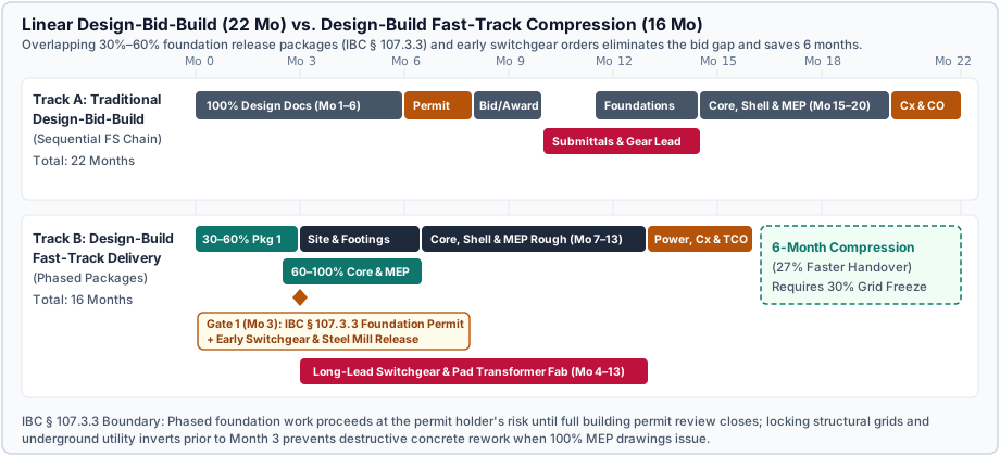
How Design-Build Schedule Compression Works: Phased Release Packages and IBC Section 107.3.3
Owners frequently choose design-build delivery for design-build schedule compression—overlapping design and construction rather than waiting for 100% construction documents before soliciting bids. As documented in the WBDG Design-Build Project Delivery Guide and empirical project benchmarks in the FHWA Design-Build Effectiveness Study, schedule compression is achieved through two distinct mechanisms:
- Eliminating the Design-to-Bid Procurement Gap: In linear Design-Bid-Build (compared in detail in our Design-Build vs. Design-Bid-Build guide), the owner completes 100% drawings, advertises for bids, evaluates tenders, and executes a construction contract before a single shop drawing or material order is placed. Design-build integrates the designer and builder under one contract from project inception (see the full design-build process from brief to handover).
- Phased Design Release Packages (Fast-Tracking): Instead of issuing one monolithic drawing set, the design-builder splits the work into sequential release packages that match the physical order of construction and equipment lead times. In progressive design-build delivery, early work packages are authorized via contract amendments while final Guaranteed Maximum Price (GMP) negotiations continue on interior scopes.
The Three Standard Fast-Track Release Packages
A properly structured master schedule divides fast-track design and procurement into three locked release packages:
- Package 1 (30%–50% Design Completion) — Site Grading, Underground Utilities, and Foundations: Civil grading, stormwater pollution prevention plan (SWPPP) controls, underground primary electrical/water utility sleeves, deep foundations, and spread footings are released for field construction while core/shell and interior MEP engineering advance in parallel.
- Package 2 (50%–60% Design Completion) — Early Long-Lead Procurement Release: Structural steel mill orders, medium-voltage pad-mounted transformers, 480V main switchgear, emergency generators, chillers, and custom air-handling units are released for factory fabrication based on approved basis-of-design load calculations and single-line diagrams.
- Package 3 (75%–100% Design Completion) — Superstructure, Envelope, MEP Rough-In, and Interiors: Full building permit issuance unlocks structural framing erection, exterior curtainwall/roof dry-in, above-ceiling MEP rough-in, and interior finishes.
The Statutory Risk Boundary: IBC Section 107.3.3 (Phased Approval)
Fast-tracking field foundations before 100% construction documents exist is governed by 2024 International Building Code (IBC) Section 107.3.3 (Phased Approval). Under IBC Section 107.3.3, the building official is authorized to issue a permit for the construction of foundations or any other part of a building before the construction documents for the whole structure have been submitted—provided adequate technical information and detailed statements have been filed complying with pertinent code requirements.
However, IBC Section 107.3.3 establishes an explicit statutory condition: the holder of such phased permit for the foundation or other parts of a building proceeds at the holder’s own risk and without assurance that a permit for the entire structure will be granted.
In schedule terms, IBC Section 107.3.3 creates a hard Interface Freeze Gate before Package 1 can be released:
- Dominant Failure Mode: Releasing foundation concrete pours at 30% design before locking structural column reactions, seismic lateral bracing loads, elevator pit dimensions, or under-slab plumbing and electrical ductbank inverts. If 90% MEP or structural plan check forces larger footing pads or relocated underground conduits, the project suffers destructive concrete saw-cutting, structural retrofit, and immediate critical-path delay.
- Engineering Rule of Thumb: Never allow
PRM-2010(Phased Foundation Permit Release) to start in the master schedule until the 30% Design Freeze milestone explicitly certifies signed sign-off on: (1) structural grid and maximum gravity/lateral foundation loads, (2) underground utility entry locations and invert elevations, and (3) total connected electrical service ampacity (kVA).
Takeaway: Fast-tracking compresses calendar duration only when interface freeze gates lock underground utilities, structural grids, and electrical service loads before the IBC Section 107.3.3 foundation permit is pulled.
Forward Pass, Backward Pass, and Total Float: Reading the Critical Path Without Software Black Boxes
When a contractor submits a baseline schedule or monthly update, owners who rely solely on visual bar charts cannot tell whether the critical path is genuine or artificially constrained. By applying the CPM Precedence Diagram Method equations codified in GAO-16-89G, you can audit any schedule network in minutes.
The Four Core CPM Equations
Every activity $i$ in a CPM network has an Original Duration ($OD_i$) measured in working days and four calculated boundary dates:
-
Forward Pass (Early Start $ES_i$ and Early Finish $EF_i$): Moves from project start (
Day 0) to completion to establish the earliest date each activity can physically occur. For Finish-to-Start (FS) predecessors $p \in Pred(i)$ with lag $Lag_{p,i}$: $$ES_i = \max_{p \in Pred(i)} \left( EF_p + Lag_{p,i} \right)$$ $$EF_i = ES_i + OD_i$$ -
Backward Pass (Late Finish $LF_i$ and Late Start $LS_i$): Moves backward from the terminal milestone ($LF_{end} = EF_{end}$) to determine the latest date each activity can finish without delaying overall project handover. For Finish-to-Start (
FS) successors $s \in Succ(i)$: $$LF_i = \min_{s \in Succ(i)} \left( LS_s - Lag_{i,s} \right)$$ $$LS_i = LF_i - OD_i$$ -
Total Float ($TF_i$): The maximum number of working days an activity can be delayed from its Early Start without delaying the overall project completion date: $$TF_i = LS_i - ES_i = LF_i - EF_i$$
-
Free Float ($FF_i$): The number of working days an activity can slip without delaying the Early Start of any immediate successor: $$FF_i = \min_{s \in Succ(i)} \left( ES_s - Lag_{i,s} \right) - EF_i$$
Any continuous chain of activities where $TF_i = 0$ (or the lowest total float in a constrained network) forms the Critical Path.
Worked Calculation Example: Structural Path vs. Electrical Switchgear Path
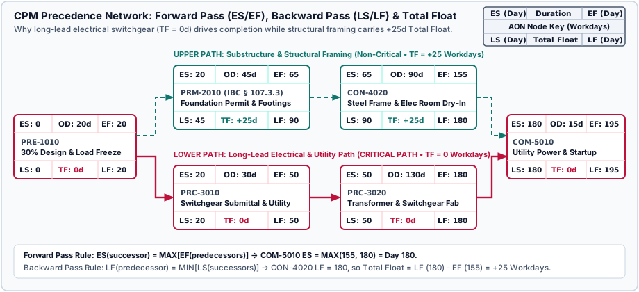
Consider the converging fast-track network shown in Figure 2 following PRE-1010: 30% Design & Load Freeze ($ES = 0, OD = 20, EF = 20$):
- Upper Path (Field Substructure & Structural Framing):
PRM-2010(IBC § 107.3.3 Foundation Permit & Footings): $ES = 20, OD = 45 \Rightarrow EF = 20 + 45 = 65$.CON-4020(Steel Frame & Electrical Room Dry-In): $ES = 65, OD = 90 \Rightarrow EF = 65 + 90 = 155$.
- Lower Path (Long-Lead Electrical Switchgear & Utility Procurement):
PRC-3010(Switchgear Submittal & Utility Engineering): $ES = 20, OD = 30 \Rightarrow EF = 20 + 30 = 50$.PRC-3020(Pad Transformer & Main Switchgear Fabrication): $ES = 50, OD = 130 \Rightarrow EF = 50 + 130 = 180$.
- Convergence at
COM-5010(Permanent Utility Power & HVAC Startup, $OD = 15$):- Forward Pass: Because permanent power energization requires both a dried-in electrical room (
CON-4020, $EF = 155$) and delivered switchgear/transformer equipment (PRC-3020, $EF = 180$): $$ES_{\text{COM-5010}} = \max(155, 180) = \text{Day } 180 \implies EF_{\text{COM-5010}} = 180 + 15 = \text{Day } 195$$ - Backward Pass: Setting $LF_{\text{COM-5010}} = 195$ and $LS_{\text{COM-5010}} = 180$:
- For
PRC-3020on the lower path: $LF = 180, EF = 180 \implies TF = 180 - 180 = 0\text{ workdays}$ (CRITICAL). - For
CON-4020on the upper path: $LF = 180, EF = 155 \implies TF = 180 - 155 = +25\text{ workdays}$ (NON-CRITICAL).
- For
- Forward Pass: Because permanent power energization requires both a dried-in electrical room (
This math exposes a critical operational reality: a 15-workday weather or steel erection delay on the upper path consumes float ($25 - 15 = +10\text{d}$ remaining) without moving the project handover date by a single day. Conversely, a 5-workday delay by the engineer or owner in approving the switchgear shop drawing (PRC-3010) directly pushes COM-5010 and final completion out by 5 workdays.
Four Schedule Manipulation Red Flags to Audit
When reviewing a contractor’s schedule update, watch for four logic distortions prohibited by GAO-16-89G and UFGS 01 32 01.00 10:
- Unpaired Start-to-Start (
SS) Links (Dangling Finishes): If Interior Drywall Hanging (OD = 30d) is linkedSS + 5dto MEP In-Wall Rough-In (OD = 40d) without a companion Finish-to-Finish (FF + 5d) restraint, the forward pass calculates drywall finishing 5 days before the in-wall rough-in finishes. Worse, if MEP rough-in slips by 20 days after starting, theSSlink never pushes the completion of drywall. - Negative Lags (Leads) Disguising Overruns: Inserting
FS - 10dbetween Roof Membrane Dry-In and energized electrical equipment installation artificially pulls the completion date left on the calendar while scheduling moisture-sensitive switchgear installation inside an unsealed building. - Long Positive Lags Hiding Unmanaged Scope: Replacing a discrete procurement chain with a single
FS + 90dlag between Contract Award and Set Switchgear hides whether submittals have been submitted, approved, released to the factory, or factory-tested. - Float Sequestering and Contract Float Ownership: Under UFGS 01 32 01.00 10 and standard design-build agreements (see our guide to design-build contract forms), Total Float is a shared project resource not owned exclusively by either party. Inflating trade durations or inserting artificial “Contractor Contingency Buffer” bars sequesters float to manufacture compensable delay claims when owner-directed changes occur.
Takeaway: Audit every Start-to-Start (SS) relationship for a pairing Finish-to-Finish (FF) restraint, reject all negative lags, and verify that Total Float is shared transparently across the network.
The Three Real Critical Path Bottlenecks: Municipal Plan Review, Utility Switchgear Energization, and Specialty Acceptance (TCO)
In modern commercial, healthcare, laboratory, and light-industrial projects, physical field erection rarely dictates the final completion date. When projects miss their turnover milestone by 3 to 9 months, the root cause almost always traces back to one of three non-structural critical path bottlenecks.
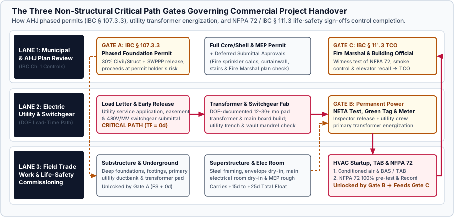
Bottleneck 1: Municipal / AHJ Plan Review, Deferred Submittals, and Phased Permit Gates
A single line item labeled “Building Permit — 30 Days” is one of the most common causes of baseline failure. Municipal permitting operates across multiple independent review queues:
- Civil, Grading & Stormwater (SWPPP): Often reviewed by the municipal engineering department or state environmental agency on a separate clock from the building official.
- Phased Foundation vs. Full Building Permit (
IBC § 107.3.3): Releasing early footings underIBC Section 107.3.3does not authorize structural steel erection or above-slab work until the core/shell plan check closes. - Deferred Submittals Trap: Under IBC Section 107.3.4, specialty engineered systems—such as automatic fire sprinkler hydraulic calculations, precast concrete stairs, curtainwall glazing, and cold-formed metal framing—are frequently designated as deferred submittals (see our responsibility guide on delegated design vs. design-assist). If the master schedule fails to track engineering preparation, Designer of Record approval, and the Fire Marshal or AHJ’s 20-to-30 workday deferred review window, field crews cannot pass framing or rough-in inspections even if the materials are on site.
Bottleneck 2: Utility Interconnection & Long-Lead Electrical Equipment (Switchgear & Transformers)
According to the U.S. Department of Energy Distribution Transformers Supply Chain Analysis, procurement lead times for pad-mounted distribution transformers expanded from historical 3-to-6 month windows to 12 to 30+ months (and 120 to 144+ weeks for large substation power transformers) due to grain-oriented electrical steel shortages, surging industrial/data-center demand, and over 80,000 utility-specific specification variations. Medium-voltage and 480V main switchboards, automatic transfer switches, and chillers face parallel bottlenecks.
To prevent utility power from stalling handover, the master schedule must model the 6-Step Utility Energization Chain as a dedicated zero-float sequence starting during 30% preconstruction:
- Electrical Load Letter & Utility Service Application (30% Design): Submit connected and demand
kVAloads, fault-current calculations, and site primary routing to the electric utility. - Utility Engineering & Easement Execution: Complete utility primary distribution engineering, execute utility right-of-way easements (which often require owner legal and lender sign-off), and pay utility aid-to-construction fees.
- Early Switchgear & Transformer Release (Package 2): Approve shop drawings and issue factory fabrication release at 50% design rather than waiting for 100% MEP construction documents.
- Civil Ductbank, Vault Installation & Utility Trench Inspection: Pour the transformer pad/vault, install primary underground conduits, pull a test mandrel, and pass utility civil inspection.
- Electrical Room Dry-In, NETA Testing & Municipal “Green Tag” Inspection: Seal the main electrical room weather-tight, set and torque main switchgear, complete third-party insulation resistance/megger testing, and obtain the local electrical inspector’s utility release tag.
- Utility Crew Scheduling & Primary Meter Energization: Utility line crews pull primary conductors, set the utility transformer/meter, and energize permanent building power.
Bottleneck 3: Specialty Inspections, NFPA 72 Acceptance, Commissioning, and IBC Section 111.3 TCO
Compressing project closeout into a single 10-day bar labeled “Punchlist & TCO” violates both the WBDG Building Commissioning Guide and the statutory inspection sequence required for a Temporary Certificate of Occupancy (TCO) under 2024 IBC Section 111.3.
Before a building official can issue a TCO under IBC Section 111.3 (or a final Certificate of Occupancy under IBC Section 111.2), the schedule must execute a strict Finish-to-Start (FS) chain:
$$\text{Permanent Power} \xrightarrow{FS} \text{HVAC Startup & Conditioned Air} \xrightarrow{FS} \text{TAB & Controls Point-to-Point} \xrightarrow{FS} \text{NFPA 72 100% Pre-Test} \xrightarrow{FS} \text{Fire Marshal Witness Test} \xrightarrow{FS} \text{IBC § 111.3 TCO}$$
- Why Temporary Generator Power Fails the Gate: Most AHJs and Fire Marshals will not conduct final life-safety witness testing on temporary construction generators because utility transfer switches, fire pump phase-reversal supervision, and normal/standby power transitions cannot be verified under permanent operating conditions.
- Mandatory NFPA 72 Pre-Test & Record of Completion: Under the NFPA 72 National Fire Alarm and Signaling Code, the installing contractor must complete a documented 100% pre-test of every initiating device, notification appliance, duct smoke detector, fire/smoke damper actuator, elevator recall relay, and central-station communicator—and sign the formal NFPA 72 Record of Completion—before requesting the Fire Marshal witness inspection.
- Rule of Thumb: Budget a minimum of 30 to 45 working days between permanent utility power energization (
Gate B) andIBC Section 111.3TCO issuance (Gate C) on any commercial project with ducted HVAC smoke control, elevators, and an addressable fire alarm system. Track each prerequisite on the preconstruction risk checklist.
Sample 20-Row Master Construction Schedule Template (Design-Build Commercial Facility)
The 20-row table below models a fast-track design-build commercial facility (215 working days / roughly 10.5 months from Notice to Proceed to IBC § 111.3 TCO, or scales proportionally for a 16-month industrial facility). Copy this structure directly into Excel using the 14-column formulas defined in Section 1.
Notice how Path B (Electrical Switchgear & Utility Energization, TF = 0d) drives the critical path straight into HVAC startup, NFPA 72 testing, and IBC § 111.3 TCO, while Path A (Foundations, Steel Framing, Envelope, and Interior Rough-In) carries +15d to +25d of Total Float.
Scroll horizontally to see all columns.
| WBS | Activity ID | Activity Description | Phase / Package | Resp. | OD (Days) | Pred. + Logic | ES | EF | LS | LF | Total Float | Critical Flag & Gate |
|---|---|---|---|---|---|---|---|---|---|---|---|---|
1.1 |
PRE-1000 |
Notice to Proceed (NTP) & Design-Build Kickoff | Preconstruction | Owner / DB | 0 |
— | 0 |
0 |
0 |
0 |
0d |
CRITICAL (Milestone) |
1.2 |
PRE-1010 |
30% Design Package, Grid Freeze & Utility Load Letter | Preconstruction | DB / A/E | 20 |
PRE-1000 FS+0d |
0 |
20 |
0 |
20 |
0d |
CRITICAL (30% Freeze Gate) |
1.3 |
PRE-1020 |
60% Core/Shell & Early Equipment Release Package | Preconstruction | DB / A/E | 25 |
PRE-1010 FS+0d |
20 |
45 |
35 |
60 |
+15d |
FLOAT (+15d) |
1.4 |
PRE-1030 |
100% Construction Documents & Deferred Submittal Criteria | Preconstruction | DB / A/E | 25 |
PRE-1020 FS+0d |
45 |
70 |
60 |
85 |
+15d |
FLOAT (+15d) |
2.1 |
PRM-2010 |
AHJ Plan Check & Issue IBC § 107.3.3 Foundation Permit | Permitting | AHJ / DB | 15 |
PRE-1010 FS+0d |
20 |
35 |
45 |
60 |
+25d |
FLOAT (+25d) — Gate A |
2.2 |
PRM-2020 |
Utility Interconnection Engineering & Easement Execution | Utility / AHJ | Utility / Owner | 30 |
PRE-1010 FS+0d |
20 |
50 |
35 |
65 |
+15d |
FLOAT (+15d) |
2.3 |
PRM-2030 |
Full Building Permit & Fire Sprinkler Deferred Approval | Permitting | AHJ / Fire | 20 |
PRE-1030 FS+0d |
70 |
90 |
85 |
105 |
+15d |
FLOAT (+15d) |
3.1 |
PRC-3010 |
Main 480V Switchgear & Pad Transformer Submittal Review | Procurement | DB / EOR | 30 |
PRE-1010 FS+0d |
20 |
50 |
20 |
50 |
0d |
CRITICAL (Early Release) |
3.2 |
PRC-3020 |
Structural Steel Shop Drawings, Mill Order & Fab | Procurement | Steel Sub | 35 |
PRE-1010 FS+0d |
20 |
55 |
55 |
90 |
+35d |
FLOAT (+35d) |
3.3 |
PRC-3030 |
Pad Transformer & Main Switchgear Factory Fabrication | Procurement | Elec Mfg | 130 |
PRC-3010 FS+0d |
50 |
180 |
50 |
180 |
0d |
CRITICAL (DOE Lead Path) |
4.1 |
CON-4010 |
Site Grading, Primary Utility Ductbank & Footings | Substructure | Civil / Conc | 30 |
PRM-2010 FS+0d |
35 |
65 |
60 |
90 |
+25d |
FLOAT (+25d) (At-Risk 107.3.3) |
4.2 |
CON-4020 |
Structural Steel Erection, Decking & Slab-on-Grade | Core & Shell | Steel / Conc | 35 |
CON-4010 FS+0d |
65 |
100 |
90 |
125 |
+25d |
FLOAT (+25d) |
4.3 |
CON-4030 |
Exterior Envelope, Roof Dry-In & Main Elec Room Dry-In | Core & Shell | Envelope Sub | 35 |
CON-4020 FS+0d |
100 |
135 |
125 |
160 |
+25d |
FLOAT (+25d) |
4.4 |
CON-4040 |
MEP Overhead/In-Wall Rough-In & Fire Alarm Wiring | MEP & Interiors | MEP Subs | 40 |
CON-4030 SS+10d |
110 |
150 |
130 |
170 |
+20d |
FLOAT (+20d) (Paired w/ FF) |
4.5 |
CON-4050 |
Interior Drywall, Finishes & Life-Safety Device Trim | MEP & Interiors | Interior Subs | 25 |
CON-4040 FS+0d |
150 |
175 |
170 |
195 |
+20d |
FLOAT (+20d) |
5.1 |
COM-5010 |
Set Switchgear, NETA Megger Test & AHJ Green Tag | Commissioning | Elec Sub / AHJ | 10 |
PRC-3030 FS+0d |
180 |
190 |
180 |
190 |
0d |
CRITICAL (Requires CON-4030) |
5.2 |
COM-5020 |
Utility Crew Primary Energization & Permanent Power | Commissioning | Electric Utility | 5 |
COM-5010 FS+0d |
190 |
195 |
190 |
195 |
0d |
CRITICAL — Gate B |
5.3 |
COM-5030 |
Permanent HVAC Startup, Conditioned Air & TAB | Commissioning | Mech / TAB | 10 |
COM-5020 FS+0d |
195 |
205 |
195 |
205 |
0d |
CRITICAL (WBDG Cx Sequence) |
5.4 |
COM-5040 |
NFPA 72 100% Pre-Test, Record of Completion & Witness | Commissioning | Fire Sub / AHJ | 10 |
COM-5030 FS+0d |
205 |
215 |
205 |
215 |
0d |
CRITICAL (NFPA 72 Ch. 7/14) |
5.5 |
COM-5050 |
IBC § 111.3 Temporary Certificate of Occupancy (TCO) | Handover | Building Official | 0 |
COM-5040 FS+0d |
215 |
215 |
215 |
215 |
0d |
CRITICAL — Gate C (TCO) |
Owner Schedule Review Checklist: What to Verify Before Approving the Baseline
Before signing a baseline schedule approval or releasing an early work package, run the contractor’s submission through the six-point verification checklist below. Connect these schedule gates to your cost controls in the costs and planning guides, specifically when classing the construction budget and estimate and recording action items in the preconstruction meeting agenda and action log.
Scroll horizontally to see all columns.
| Audit Dimension | Baseline Verification Question | Governing Standard / Code | Consequence if Left Unchecked |
|---|---|---|---|
| 1. WBS & Cost Alignment | Does every schedule work package map to a cost-coded line in the estimate and Schedule of Values? | GAO-16-89G Best Practice 1 (100% Rule) & UFGS 01 32 01.00 10 |
Progress billings cannot be verified against earned physical schedule milestones |
| 2. PDM Logic Integrity | Do 100% of non-milestone tasks have predecessors and successors, zero negative lags, and zero hard date constraints? | GAO-16-89G Best Practices 2 & 6; UFGS 01 32 01.00 10 |
Dangling tasks and negative leads hide critical-path delays until closeout |
| 3. Activity Granularity | Are all near-term execution activities broken into discrete durations of <= 44 working days? |
GAO-16-89G Best Practice 4 |
Long summary bars conceal trade stacking and prevent early slip detection |
| 4. IBC § 107.3.3 Freeze Gate | Are structural grids, foundation loads, and underground utility inverts frozen in writing before phased foundation release? | 2024 IBC Section 107.3.3 (Phased Approval) |
Permit holder bears full risk of concrete demolition if 100% MEP/structural review shifts loads |
| 5. Long-Lead & Utility Chain | Are switchgear, pad transformer, and HVAC submittals, factory fabrication, easement execution, and utility trench inspections shown as separate tasks? | DOE Transformer Findings & UFGS 01 32 01.00 10 Procurement Rules |
Late equipment release or unsigned utility easements stall permanent power energization |
| 6. Closeout & TCO Sequence | Is turnover broken into Permanent Power → HVAC Startup & TAB → NFPA 72 100% Pre-Test → Fire Marshal Witness → IBC § 111.3 TCO? |
2024 IBC Section 111.3, NFPA 72, & WBDG Commissioning |
Unsequenced “Punchlist” bars miss mandatory 30–45 workday life-safety testing windows |
Frequently asked questions
Why is a conditional-formatting Excel Gantt chart not a Critical Path Method schedule?
A conditional-formatting Gantt chart only shades calendar cells based on hand-typed start and finish dates. It lacks Precedence Diagram Method (FS, SS, FF) links, forward pass (ES/EF) and backward pass (LS/LF) formulas, and Total Float (TF = LS - ES) calculations, meaning a slip in an upstream permit or submittal never recalculates the project completion date.
How does IBC Section 107.3.3 affect fast-track design-build schedules?
International Building Code (IBC) Section 107.3.3 authorizes the building official to issue a phased permit for foundations or partial substructure work before 100% construction documents for the entire building are submitted. However, the code stipulates that the permit holder proceeds at its own risk and without assurance that a permit for the entire structure will be granted, making a 30% structural grid and underground utility invert freeze essential before pouring concrete.
What is the difference between Total Float and Free Float in a construction schedule?
Total Float (TF = LS - ES = LF - EF) is the number of working days an activity can be delayed from its Early Start without delaying the overall project completion milestone. Free Float is the number of working days an activity can slip without delaying the Early Start of its immediate successor activity.
Why do electrical transformers and switchgear frequently control the critical path instead of structural steel?
U.S. Department of Energy supply chain analyses document that pad-mounted distribution transformer lead times expanded from historical 3-to-6 month windows to 12 to 30+ months, with similar extensions for 480V and medium-voltage main switchgear. Because permanent utility power is a hard prerequisite for permanent HVAC startup, environmental stabilization, and life-safety acceptance testing, any delay in early electrical procurement directly delays final occupancy.
What schedule activities must finish before a building official issues a Temporary Certificate of Occupancy under IBC Section 111.3?
Under IBC Section 111.3, a Temporary Certificate of Occupancy (TCO) requires proving that the designated portion of the building can be occupied safely. In practice, that requires permanent utility power energization, permanent HVAC startup and air balancing, a completed NFPA 72 100% contractor pre-test with a signed Record of Completion, and a passed Fire Marshal and building inspector witness test of fire alarm, smoke control, sprinkler supervision, and elevator recall systems.
Related guides

Preconstruction Manager: Role and Deliverables
The preconstruction manager's job is the running set of estimates, value-engineering records, and bid-package boundaries, not the meeting agenda.
Read guide
Pre Construction Meeting: Agenda and Log
A pre construction meeting agenda and action log: topic, responsible person, record, deadline, and what is still open.
Read guide
What Is Preconstruction? Phase, Activities and Services
What the preconstruction phase covers, its activities and services, how design, estimates and procurement loop back, and who decides before work starts.
Read guide